在Unity中实现三面映射Shader
实现思路
在常规的纹理映射中,我们用于采样纹理的UV来自于网格体。但某些情况下,网格体中并没有可用的UV,例如程序化几何体,或者实时生成的地形系统。此时,我们需要其他的方法来实现纹理映射,一种常见的思路是使用三面映射。
三面映射的核心思路是利用片段的世界空间坐标来生成UV,并在不同的轴向加以不同的权重,从而生成合适的UV。
实现细节
简单三面映射
第一步,我们根据片段的世界空间坐标,创建出一组float2,分别用于在三个轴向上进行纹理映射:
1
2
3
4
5
6
7
8
9
10
11
12
13
14
15
16
17
18
19
20
21
22
23
24
25
26
27
28
29
30
31
struct TriPlanarUV
{
    float2 x;
    float2 y;
    float2 z;
};

TriPlanarUV GetTriPlanarUV(Varyings varyings)
{
    TriPlanarUV triUV;
    const float3 pos = varyings.positionWS;
    triUV.x = pos.zy;
    triUV.y = pos.xz;
    triUV.z = pos.xy;
    return triUV;
}

void TriPlanar(inout Surface surface, Varyings varyings)
{
    TriPlanarUV triUV = GetTriPlanarUV(varyings);

    float3 albedoX = SAMPLE_TEXTURE2D(_BaseMap, sampler_BaseMap, triUV.x).rgb;
    float3 albedoY = SAMPLE_TEXTURE2D(_BaseMap, sampler_BaseMap, triUV.y).rgb;
    float3 albedoZ = SAMPLE_TEXTURE2D(_BaseMap, sampler_BaseMap, triUV.z).rgb;

    const float3 blend = rcp(3);
    surface.color = 0;
    surface.color += albedoX * blend;
    surface.color += albedoY * blend;
    surface.color += albedoZ * blend;
}
基于法线混合
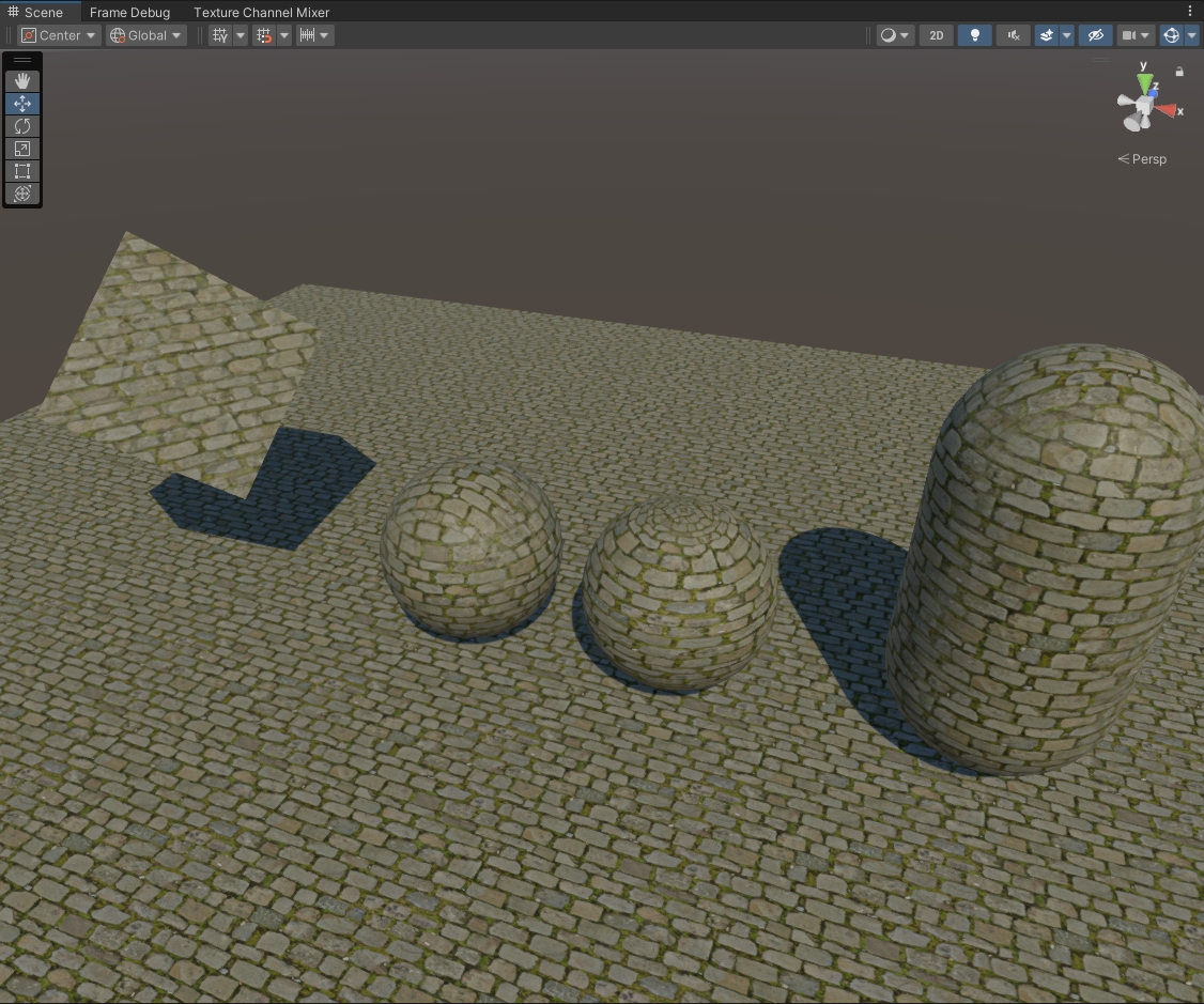
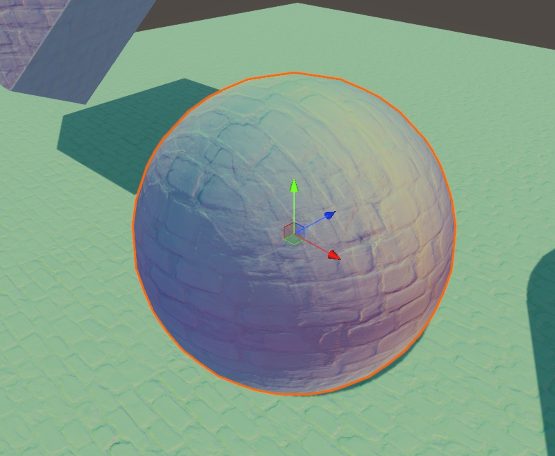
虽然我们得到了基础的三面映射,但是在纹理过渡上有这明显的接缝:
我们需要更好的方法以实现在三个纹理之间的平滑过渡。具体来说,我们应该根据片段的朝向来计算出对应的权重值。这里需要注意,我们需要获取法线的绝对值,因为片段有可能朝向负方向。此外,我们还需要考虑到权重值之和必定为1:
1
2
3
4
5
6
7
8
9
10
11
12
13
14
15
16
17
18
float3 GetTriPlanarWeights(Varyings varyings)
{
    float3 weights = abs(varyings.normalWS);
    const float sum = weights.x + weights.y + weights.z;
    weights *= rcp(sum);
    return weights;
}

void TriPlanar(inout Surface surface, Varyings varyings)
{
    ...

    const float3 blend = GetTriPlanarWeights(varyings);
    surface.color = 0;
    surface.color += albedoX * blend.x;
    surface.color += albedoY * blend.y;
    surface.color += albedoZ * blend.z;
}
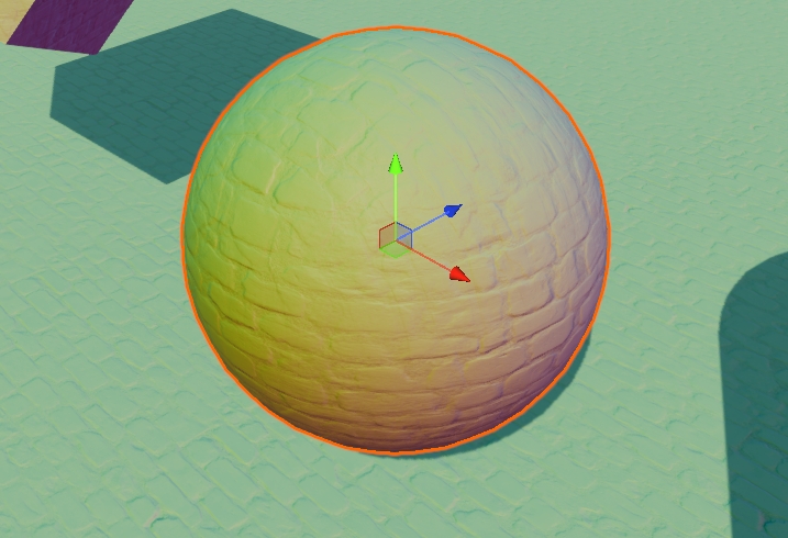
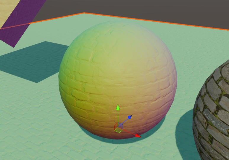
处理镜像映射
现在,我们观察材质外观,会发现因投影方向不同导致的镜像问题:
这是因为,
当表面法线指向某轴的负方向时,直接使用世界坐标会导致该轴的投影平面UV方向与其他平面不一致,进而导致纹理的观察方向相反,从而产生镜像。例如:
- 当法线为 +X 时,投影平面是ZY平面,UV为
(z, y)。 - 当法线为 -X 时,投影平面仍然是ZY平面,但此时观察方向相反,UV的
z分量(对应triUV.x.x)会反向,导致纹理镜像。
所以,我们需要根据法线方向调整UV,确保不同投影平面上的纹理方向一致:
1
2
3
4
5
6
7
8
9
10
11
12
TriPlanarUV GetTriPlanarUV(Varyings varyings)
{
    ...

    // avoid mirrored UV
    // -----------------
    if (varyings.normalWS.x <  0) triUV.x.x = -triUV.x.x;
    if (varyings.normalWS.y <  0) triUV.y.x = -triUV.y.x;
    if (varyings.normalWS.z >= 0) triUV.z.x = -triUV.z.x;

    return triUV;
}
处理映射偏移
由于我们是将一个相同的纹理进行了三次映射,有可能我们在场景中能看到较为明显的重复,我们可以选择对映射进行一定程度的偏移,减弱映射效果。
1
2
3
4
5
6
7
8
9
10
11
TriPlanarUV GetTriPlanarUV(Varyings varyings)
{
	...

    // offset UV
    // ---------
    triUV.x.y += 0.33;
    triUV.z.x += 0.33;

    return triUV;
}
法线贴图的三面映射
在我们研究法线的三面映射之前,可以先看一下Standard Lit Shader中的法线的实现方式:
- 采样法线贴图,获取切换空间下的法线信息
- 根据物体空间下的法线与切线信息,构建TBN矩阵
- 将切线空间下的法线信息转换到世界空间
- 在世界空间中计算光照
那么在处理法线贴图的三面映射是,思路也是一致的,首先就是采样三次法线贴图,以便获取三个轴向对应的切线法线:
1
2
3
float3 tangentNormalX = GetNormalTS(triUV.x);
float3 tangentNormalY = GetNormalTS(triUV.y);
float3 tangentNormalZ = GetNormalTS(triUV.z);
记下来,我们可以先做一次简单的“切线空间-世界空间”变换,跑通变换流程,看看效果再说:
1
2
3
4
5
float3 worldNormalX = tangentNormalX;
float3 worldNormalY = tangentNormalY;
float3 worldNormalZ = tangentNormalZ;
surface.normal = normalize(worldNormalX * blend.x + worldNormalY * blend.y + worldNormalZ * blend.z);
surface.color = surface.normal * 0.5 + 0.5;
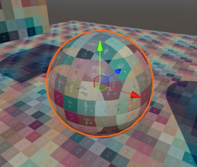
如我们所想,因为我们并没有做实际上的空间变换,所得到的结果是切线空间中的法线,如下图所示:

之所以呈现出蓝色,是因为切线空间法线存储在物体自身的up方向,也就是Z轴。对我们目前“简单”的法线空间变换来说,只有在Z轴上的映射是正确的,我们需要首先调整另外两个轴向的swizzle:
1
2
3
float3 worldNormalX = tangentNormalX.zyx;
float3 worldNormalY = tangentNormalY.xzy;
float3 worldNormalZ = tangentNormalZ;
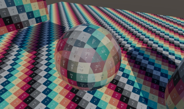
修改的效果是显而易见的:
在创建三面映射UV时,我们就根据法线朝向调整了UV的X分量,从而解决了错误的镜面映射效果。对于法线的处理是类似的。此外,我们还需要额外判断是否需要反转法线的Up方向:
1
2
3
4
5
6
7
8
9
10
11
12
13
14
15
16
17
18
if (varyings.normalWS.x <  0)
{
    tangentNormalX.x = -tangentNormalX.x;
    tangentNormalX.z = -tangentNormalX.z;
}
if (varyings.normalWS.y <  0)
{
    tangentNormalY.x = -tangentNormalY.x;
    tangentNormalY.z = -tangentNormalY.z;
}
if (varyings.normalWS.z >= 0)
{
    tangentNormalZ.x = -tangentNormalZ.x;
}
else
{
    tangentNormalZ.z = -tangentNormalZ.z;
}
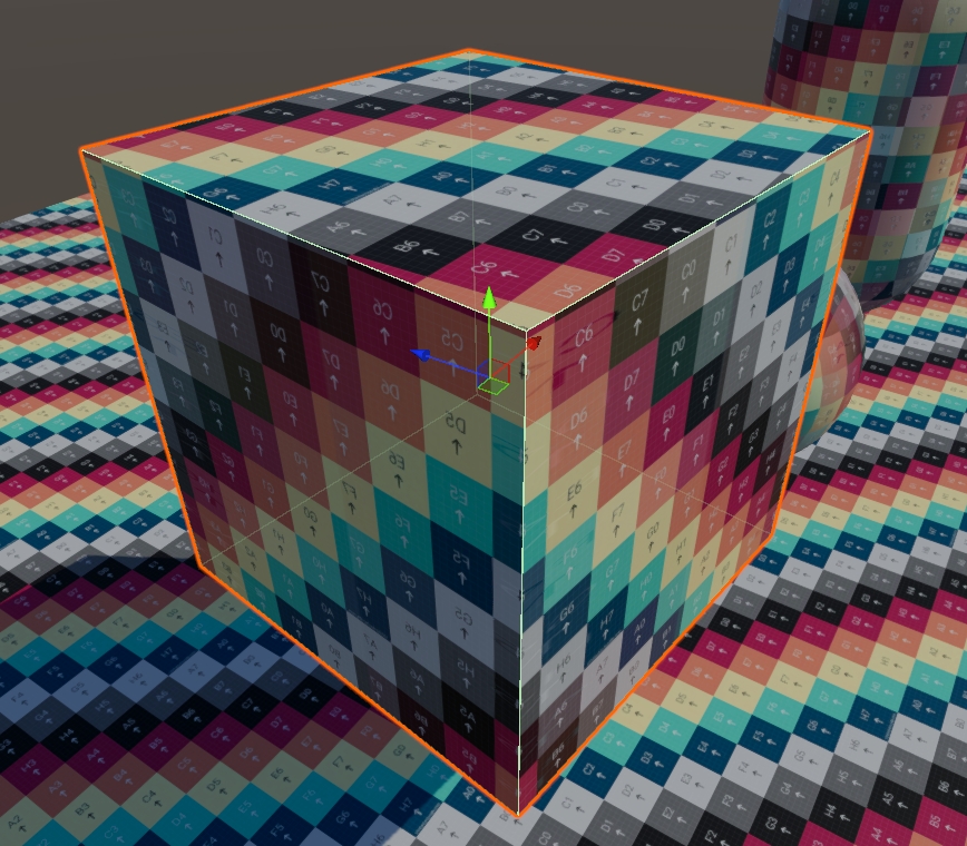
这样,我们就得到了正确的法线三面映射:
与表面法线混合
目前,我们已经实现了法线贴图的三面映射,但是还没有正确地处理与实际表面法线之间的关系。
一般情况下,我们都是通过“切线空间-世界空间”的变换矩阵,以实现法线对几何体表面的适应。但这并不适用于三面映射的情况。所以,我们转而可以尝试通过whiteout方式混合映射法线与表面法线。
1
2
3
4
5
6
7
8
9
10
11
12
13
14
15
16
17
float3 BlendTriPlanarNormal(float3 mappedNormal, float3 surfaceNormal)
{
    float3 n;
    n.xy = mappedNormal.xy + surfaceNormal.xy;
    n.z  = mappedNormal.z * surfaceNormal.z;
    return n;
}

void TriPlanar(inout Surface surface, Varyings varyings, InputConfig config)
{
    ...
    float3 worldNormalX = BlendTriPlanarNormal(tangentNormalX, varyings.normalWS.zyx).zyx;
    float3 worldNormalY = BlendTriPlanarNormal(tangentNormalY, varyings.normalWS.xzy).xzy;
    float3 worldNormalZ = BlendTriPlanarNormal(tangentNormalZ, varyings.normalWS);
    surface.normal             = normalize(worldNormalX * blend.x + worldNormalY * blend.y + worldNormalZ * blend.z);
    surface.interpolatedNormal = normalize(varyings.normalWS);
}
现在,我们需要再次调整朝向负轴向的片段,因为我们目前已经乘以了两次负的Z值,反转了最终的Z的轴向,所以,正确地做法是不处理负的Z值,这样就负负得正了
Tilling
这里就不再引入额外的材质属性了,直接使用BaseMap的Tiling的X分量作为缩放值即可:
1
2
3
4
5
6
7
8
9
10
11
TriPlanarUV GetTriPlanarUV(Varyings varyings)
{
    // get basic uv from positionWS
    // ----------------------------
    TriPlanarUV triUV;
    const float3 pos = varyings.positionWS * _BaseMap_ST.x;
    ...

    return triUV;
}
权重优化
为权重引入偏移量,进行指数重映射,并读取高度贴图进行加乘。这里就不再展示对应的代码了。